ESP-01S Smart Switch using a Relay
I bought an ESP-01S with a relay module from AliExpress so that I could make my own smart switch.
The relay will be controlled by Home Assistant in the first version, there are some similarities to my project on temperature reporting and I will be following a similar approach.
The simple way to do this project is actually to install ESPHome and then configure there, but then where is the fun in that?!
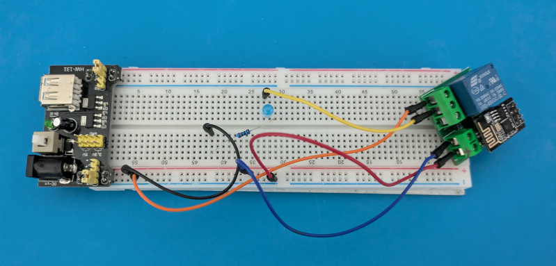
ESP-01S Relay Circuit
Testing
First I needed to test that the relay worked as expected.
/**
 * ESP-01S Relay test
 * Relay in Normally Open configuration
 * Alternate between on and off for 2 second intervals
 */

// GPIO pin number
const int relayPin = 0;

void setup()
{
  Serial.begin(115200);
  pinMode(relayPin, OUTPUT);
}

void loop()
{
  digitalWrite(relayPin, LOW);
  Serial.println("Relay ON");
  delay(2000);

  digitalWrite(relayPin, HIGH);
  Serial.println("Relay OFF");
  delay(2000);
}
Compile and upload the code in the usual way.
The above sketch works but I learned a few tricks:
- The relay board needs 5V input. I was trying to be careful not to fry my ESP so I had started with 3.3V input.
- In my big cheap bag of jumper wires some of them are not good so make sure to check continuity before building circuits otherwise you will waste time trying to track down errors.
Remote Switching
Now I wanted to make the relay controllable remotely using MQTT.
I am using the AsyncMQTT library, ESP-32/ESP-8266 version, installed into the Arduino IDE. I also needed to install the ESPASyncTCP library. The idea is that the ESP-01S will subscribe to a topic on the MQTT broker which will control the state of the relay.
/**
 * @file   relay_mqtt.ino
 * @brief  ESP-01S Remote Relay using MQTT
 * @author Lyndon Hill
 * @date   2024.10.06
 */

#include <ESP8266WiFi.h>
#include <AsyncMqtt_Generic.h>
#include "general.h"

// MQTT Topic to subscribe, that will control relay
const char *subTopic = "lh-mqtt/relay";

// GPIO pin number that operates relay
// This file uses Normally Open configuration.
// If you want to use Normally Closed then you need to change the logic
// state between LOW and HIGH for every line that uses relayPin and
// add a comment here
const int relayPin = 0;

WiFiClient espClient;
AsyncMqttClient mqttClient;

void setupWifi() {
  delay(10);
  WiFi.begin(MY_SSID, MY_WIFI_PASSWORD);
  while(WiFi.status() != WL_CONNECTED) {
    delay(500);
  }
}

void connectMqtt()
{
  Serial.println("Connecting to MQTT...");
  mqttClient.connect();
}

void onMqttConnect(bool sessionPresent)
{
  Serial.print("Connected to MQTT broker: "); Serial.print(MQTT_HOST);
  Serial.print(", port: "); Serial.println(MQTT_PORT);

  mqttClient.subscribe(subTopic, 0);
  Serial.print("Session present: "); Serial.println(sessionPresent);
}

void onMqttSubscribe(const uint16_t &packetId, const uint8_t &qos)
{
  Serial.println("Subscribe acknowledged.");
  Serial.print("  packetId: ");
  Serial.println(packetId);
  Serial.print("  qos: ");
  Serial.println(qos);
}

void onMqttMessage(char *topic, char *payload, const AsyncMqttClientMessageProperties &properties,
                   const size_t &len, const size_t &index, const size_t &total)
{
  Serial.println("Publish received.");
  Serial.print("  topic: ");  Serial.println(topic);
  Serial.print("  qos: ");    Serial.println(properties.qos);
  Serial.print("  dup: ");    Serial.println(properties.dup);
  Serial.print("  retain: "); Serial.println(properties.retain);
  Serial.print("  len: ");    Serial.println(len);
  Serial.print("  index: ");  Serial.println(index);
  Serial.print("  total: ");  Serial.println(total);

  String content = "";
  for(size_t i = 0; i < len; i++)
  {
    content.concat(payload[i]);
  }
  Serial.print(content);
  Serial.println();

  // Set the relay according to Normally Open configuration
  if(content == "ON") {
    digitalWrite(relayPin, LOW);
    Serial.println("Switched on");
  }

  if(content == "OFF") {
    digitalWrite(relayPin, HIGH);
    Serial.println("Switched off");
  }
}

void onMqttDisconnect(AsyncMqttClientDisconnectReason reason)
{
  (void) reason;

  Serial.println("Disconnected from MQTT.");
}

void setup()
{
  Serial.begin(115200);
  pinMode(relayPin, OUTPUT);

  mqttClient.onConnect(onMqttConnect);
  mqttClient.onDisconnect(onMqttDisconnect);
  mqttClient.onSubscribe(onMqttSubscribe);
  mqttClient.onMessage(onMqttMessage);
  mqttClient.setServer(MQTT_HOST, MQTT_PORT);

  setupWifi();
  connectMqtt();

  digitalWrite(relayPin, HIGH); // Switch off at start up (Normally Open)
}

void loop()
{
}
The file general.h contains the following lines that you will need to edit:
#define MY_SSID "your wifi SSID here"
#define MY_WIFI_PASSWORD "your wifi password here"
#define MQTT_HOST "MQTT host IP address, e.g. 192.168.0.10"
#define MQTT_PORT 1883
With this sketch uploaded I now wanted to test it by publishing an MQTT message to switch the relay. As I had previously installed mosquitto on my Raspberry Pi, I opened a terminal and entered mosquitto_pub -t 'lh-mqtt/relay' -m 'ON' allowing me to confirm I could control the relay.
Note that this code can be made more robust to network drop outs.
Node-Red
I wanted to try controlling the relay using Node-Red. I installed the Node-Red docker image and started it.
I will let you find one of many tutorials on Node-Red to learn how to use it. For this simple application it did not take long to work out the following steps:
- From the settings I installed the node-red-dashboard module, this is required to add user interface controls,
- I added a new dashboard,
- I added a switch and an 'MQTT in' node, (see the image below)
- I configured the nodes to use the MQTT topic and MQTT broker that I had previously set up,
- I deployed the flow
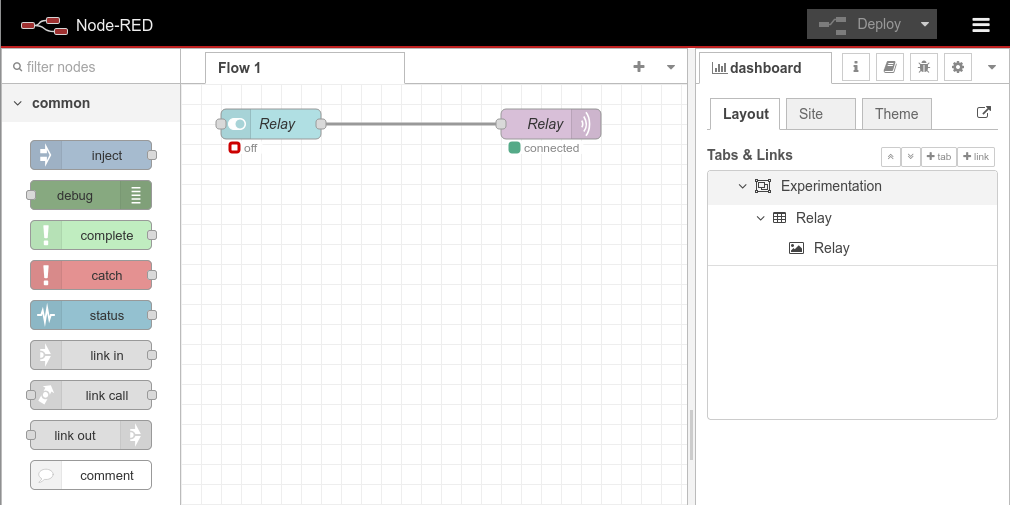
Node-Red Flow for Controlling the Relay
Pointing my web browser at the Node-Red deployment gave me a working UI, even if it is a simple switch. This enabled me to confirm Node-Red was working.
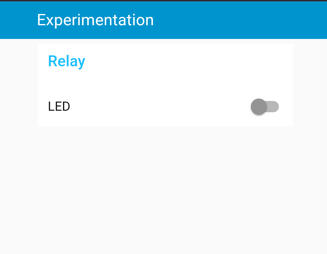
Deployed Flow shown on Android Chrome
Integrating into Home Assistant
This part is actually very easy, provided you have already installed the MQTT integration in Home Assistant and set it up, like in my previous temperature monitoring project.
Edit your Home Assistant configuration.yaml file to add the following; if you already have added MQTT configuration, you can edit it underneath. Just watch out for the indents. Then restart Home Assistant for the changes to take affect.
mqtt:
  switch:
    - name: "LCD Relay"
      qos: 0
      retain: true
      command_topic: "lh-mqtt/relay"
      icon: mdi:electric-switch
This is really basic; you can set up a state_topic such that the true state of the relay is always shown in Home Assistant. You'll need to modify the sketch to publish the topic and set the topic in the configuration YAML.
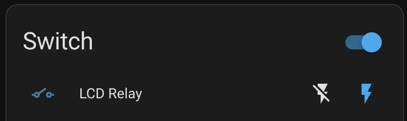
How the relay is controlled from Home Assistant
< Back