Stereo Camera Systems
Contents
- Hardware Design
- Synchronisation
- Calibration
- Colour Correction
- Creating Stereo Video Content
- 3D Reconstruction
Introduction
For 3D model acquisition from images at least 2 views of a scene from different overlapping viewpoints are required, but multiple images are needed in order to make a 3D model with enough detail to be manipulated and viewed from arbitrary poses. While humans use stereo vision to perceive depth, computer based vision systems can use a single moving camera or multiple cameras to infer depth.
These days, AI models can infer depth from a single image with somewhat reasonable quality and are getting better at using a single image to approximate scenes to synthesise realistic looking views from a limited range of poses.
Building an Asymmetrical Stereo Camera System
Stereo cameras are great for building 3D models and maps for robotics applications; although the design of the camera should be customised to the task in terms of sensor resolution, baseline, focal length, aperture, etc in order to optimise for accuracy and capture volume.
Previously, I have worked on the design and development of the software and hardware for SubSLAM, an underwater stereo camera system used on ROVs and AUVs for subsea survey and inspection. I have also written software that guides users to take stereo photographs with one moving camera, and implemented my algorithm on the Sharp SH505i mobile phone as it had an autostereoscopic display.
For stereo content, the baseline (distance between cameras) needs to match the interocular distance which is on average about 65mm. Larger distances will be uncomfortable to view and for considerably larger distances it will not be possible to fuse the two views and perceive 3D. For mapping and robotics the choice of baseline can be more flexible but lens characteristics and sensor resolution will limit accuracy and volume captured at any instant.
I wanted to build a stereo camera system for 3D model building and stereo content but the only suitable cameras available to me were two GoPro action cameras with different generations of technology, different lenses and no way to synchronise electronically. This represented a number of challenges that were tackled in this project.
All necessary code, scripts and data files used in this project can be found shared on my github account,
Camera Settings
The two models of GoPro I have are the Hero 3+ Silver edition and Hero 10. Settings were adjusted to maximise feature matching between cameras,
- The Hero 3+ is not capable of capturing 4K resolution video, therefore both cameras were set to capture at 1920×1080,
- Sensor sensitivity set to specific values rather than auto,
- Colour profile set to flat with a fixed temperature for white balance,
- Lens mode set to Wide; not Linear or Superview as those are digitally processed,
- Video stabilisation disabled (Hero 10),
- Protune set to high bitrate and medium sharpness (Hero 10),
- Frame rate set to at least 50 Hz to reduce inter view motion and to make the video finer grained for easier syncing
Lower frame rates could be used but I would not recommend using less than 50 Hz.
Hardware Design
I found this dual GoPro mount and printed it on my 3D printer. The baseline when using this rig for my asymmetrical camera is approximately 86mm.
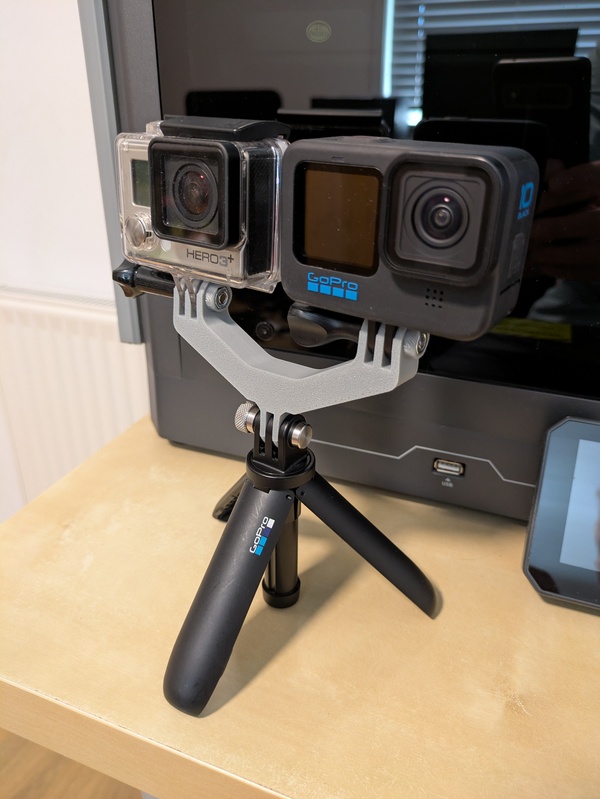
Off the Shelf Dual Mount, on a GoPro Shorty
Unfortunately, for my use case this mount has several issues. Firstly, the Hero 3+ has to be mounted in its protective case which is not ideal. Secondly, if I need to access the memory cards or batteries I must remove the cameras from the mount and it would be difficult to replace them in the exact same alignment, breaking calibration. Thirdly, the lenses are not vertically level.
Improved Rig
I knew that synchronisation would be required for every capture, I planned to automate that by software. Using this mount meant that calibration would also be required for every capture and that would quickly become tedious, therefore a better mount was required.
I designed my own mount with the following objectives:
- Both lenses are vertically aligned to improve rectification and reduce cropping
- The Hero 3+ can be used without the protective case
- The cameras will be held securely with minimal movement so that calibration can be maintained
- Reduce the baseline from 86mm to be closer to 65mm
- Keep controls accessable
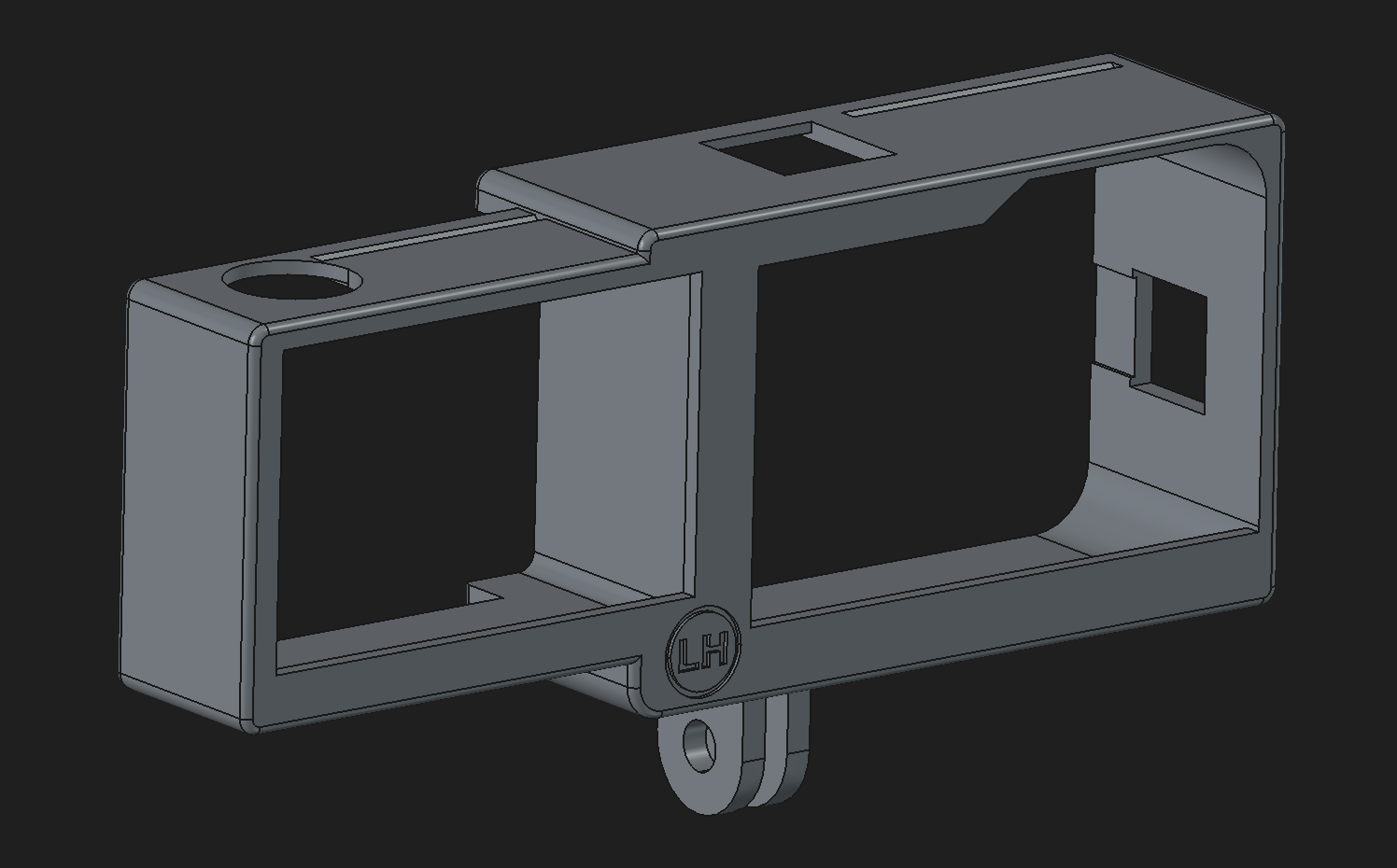
Custom Design, made with FreeCAD
The new mount is printed in PETG and has a baseline of 72mm. It took a few iterations to get all the holes lined up and the tolerances to give a good fit. It is much easier to use than the previous mount - cameras can be inserted and removed quickly.
I should note that GoPro produced a (now discontinued) official stereo mount and sync electronics. I could have positioned one of the cameras upside down in a similar fashion in order to achieve the 65mm baseline but then some of the controls would be upside down - which is not a problem for the official solution as the sync box allows one camera to control the other. The mount would also be wider and taller.
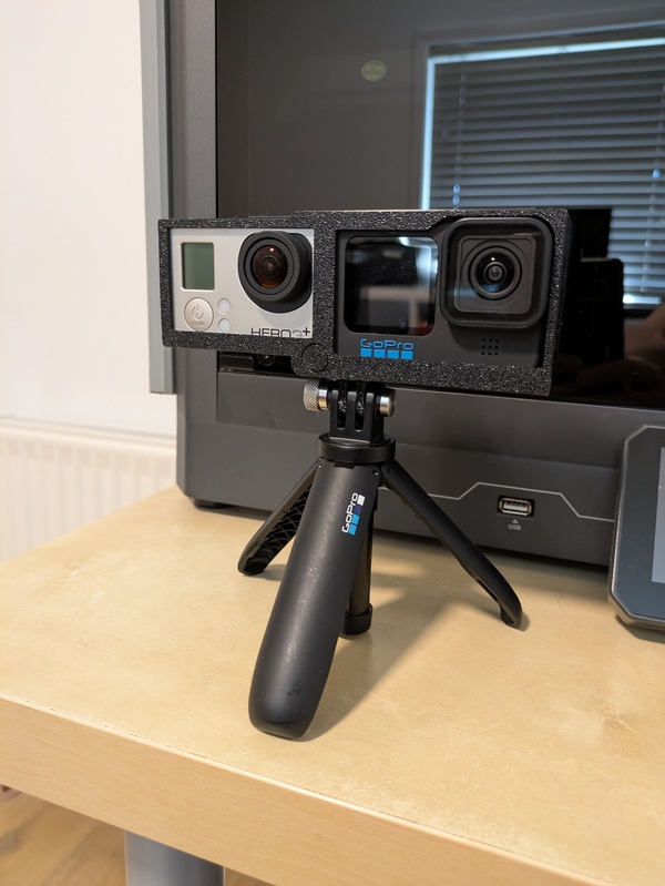
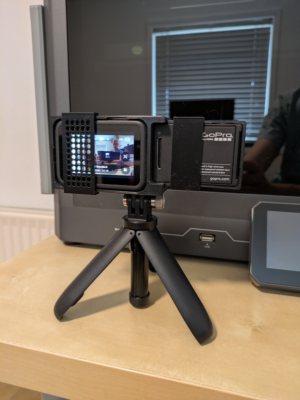
Custom Design, front and back view
Clips snap on the back of the mount to keep the cameras in the mount. This design seems to work well but is probably not strong enough for situations with very fast movements or strong vibrations. The clip for the Hero 10 side has holes so that the back screen is not completely blocked. Additional clearance has been added around the buttons to avoid scratching them and also near the Hero 10 battery door.
The total cost of filament was £0.55 and took 1 hour, 21 minutes and 40 seconds print time. The weight of the bare rig is 58g and with cameras and my GoPro Shorty tripod, 330g. In future work I may add a cold shoe mount at the top, redesign the clips so that they are an integrated part of the mount and add lens hoods. In the mean time, it is more important to gain real world experience with it and find what works and what does not work.
I make my designs available to download via thingiverse.
Synchronisation
Synchronisation is vital if the camera is moving otherwise there will be motion between the two views. Ideally sync would be performed electronically. With more modern GoPro cameras it is possible to sync GoPro cameras using GoPro's QR code based visual configuration service for precision time, unfortunately this is not available for the older Hero 3+ model.
Timing Reference
By pointing both cameras at the GoPro precision time website on a computer screen or phone, I could view the time difference between recordings on the two cameras. The white background to the website made exposure difficult so I switched to using the stopwatch app on my Android phone which has a dark theme and automatically stops the phone going to the lock screen.
Automatic Alignment
It is possible to manually align videos by looking for frames with the same digits visible in both views. Manual alignment was accurate but quite tedious and some judgement was required to choose the closest matching frames especially when the onscreen digits were transitioning to a new value.
I automated the process by using the audio: The first 10 seconds of audio are extracted from each video, mixed down to mono and downsampled to 16 kHz. Then using the cross-correlation function implemented in scipy I could work out the offset. After starting recording on both cameras I clap my hands so that there is a clear signal to correlate. I experimented with finger snapping for situations where I can only use one hand but the correlation was not as strong. When the conditions are right (not too much ambient noise) finger snapping could be used.
There were some nuances about rounding precision when choosing exactly which frames to extract; this was further complicated when I discovered that some of the frames extracted from Hero 3+ video at 50 Hz using FFmpeg would be repeated near the start of the video. I added "trim" parameters to my synchronisation code and they seem to work reasonably well.
Synchronisation Processing
The synchronisation script, stsync.py will extract synchronised images from the video and output to the test-rig/left and test-rig/right directories:
stsync.py --left GX000001.MP4 --right GOPR0001.MP4 --output test-rigCalibration
Images can automatically be selected from video of a calibration chart. As long as the images are suitable (in focus, chart visible in both views) then extrinsics can be estimated. Intrinsics can be estimated separately in advance. All necessary details explaining this process and code can be found via my calibration demo page. I had computed intrinsic calibrations for both cameras and therefore already had a suitable calibration chart.
For GoPros in Wide lens mode the fisheye model should be best: in theory this should work in a straightforward manner. In practice I found that the fisheye model was highly sensitive when corners of the calibration chart were close to the edges of the frame or the chart had a large amount of skew. The calibration tool would report good RMS projection error for the intrinsics but the lens parameters were overfitted resulting in the dedistortion tool being unable to produce a good image. There were also cases where intrinsics that were good for dedistortion were not good for matching views when running Structure from Motion. I ran mono reconstructions using COLMAP on single views to verify that intrinsics were good.
Despite difficulties using the fisheye model, I have used it throughout this project and all my code assumes that it is the model used.
Process
Set up for extrinsics calibration:
- Configure the cameras, as mentioned previously
- Install cameras in stereo mount
- Start both cameras recording
- Clap hands or snap fingers within the first 10 seconds of recording
- Record video of the chart moving the camera slowly in front of the calibration chart.
Extract synchronised images from the video using the stsync.py script as shown in the previous section.
Select frames of the calibration with different angles; run the select.sh script on both views, for example if the calibration images are between frames 100 and 200 and you want to use every 5th frame:
select.sh test-rig/left/frame%05d.jpg calibration-rig/left 100 5 200
select.sh test-rig/right/frame%05d.jpg calibration-rig/right 100 5 200
Ensure that the calibration-rig directory contains enough image pairs where all of the calibration chart is visible in frame for both views and sharp focus in each image. Typically I move the cameras around the chart, slowly and then select about 100 frames.
Run extrinsic calibration using fisheye model, e.g. if left.yaml contains the left intrinsics and right.yaml contains the right intrinsics:
calibrate_stereo -i test-rig -a left.yaml -b right.yaml -c stereo.yaml -fThe extrinsics will be output to stereo.yaml. The calibrate_stereo tool can output a stereo rig file in COLMAP format using the -r parameter. This is a feature I added as I anticipated it would be useful for this project.
A Calibrated Mount
You could now assume that calibration will be preserved even if the cameras are removed from the mount. For situations where I need the highest accuracy I will calibrate extrinsics every time the cameras are installed in the mount.
As calibration is a process that you don't want to be doing all the time, then it is important to get a good calibration. If the cameras are pointing at a time reference during synchronisation, like the stopwatch app mentioned earlier, then it is possible to see how close the time between starting the 2 recordings was to a multiple of the frame period. The images can capture the display tranisitioning to the new time and if most of the images clearly show the same transition in an image pair then the sync is good and this is more likely to lead to a good calibration.
Colour Correction
Mismatched colour between the two cameras is likely as they are using different sensors and different ISPs. This may lead to poor inter-view matching for 3D reconstruction. It may also cause binocular rivalry when viewing stereo content: the colour differences in the views seen by each eye could be enough to prevent fusion and break stereopsis.
By capturing video of various colourful scenes and matching between views a 3D Look Up Table (LUT) is learned which can then be used to quickly convert right camera images to a similar colour balance to the left camera. The LUT only needs to be computed once and it is not necessary to sample every possible combination of colour components, only a spread of values across the colour gamut. When using the LUT trilinear interpolation is used to sample the exact look up.
Process
For LUT generation,
- Load a pair of synced images
- Find matching points between the 2 images
- Drop matches that correspond to independently moving objects
- Reject pixels that are saturated, in shadows or clipped highlights
- Fit a nonlinear model to the matched values
- Build an RGB cube and transform it with the model
- Save the transformed cube as the LUT
Usage
Using this method, a LUT can be created in the standard cube format using the generate_lut.py script:
generate_lut.py -i test-rig -o lut.cubeI used scikit-learn for the model fitting and colour-science to handle 3D LUTs. The output LUT file can be used to process a directory full of images:
apply_lut.py -i input_directory -l lut.cube -o output_directoryThis is really convenient as FFmpeg can make use of this LUT file by using the lut3d filter, e.g.
ffmpeg -i input.mp4 -vf "lut3d=lut.cube" output.mp4This is already integrated into stsync.py via the --lut parameter so that I can extract synchronised and colour corrected images at the start of processing and not have to worry about it again,
stsync.py --left GX000001.MP4 --right GOPR0001.MP4 --lut lut.cube --output test-rig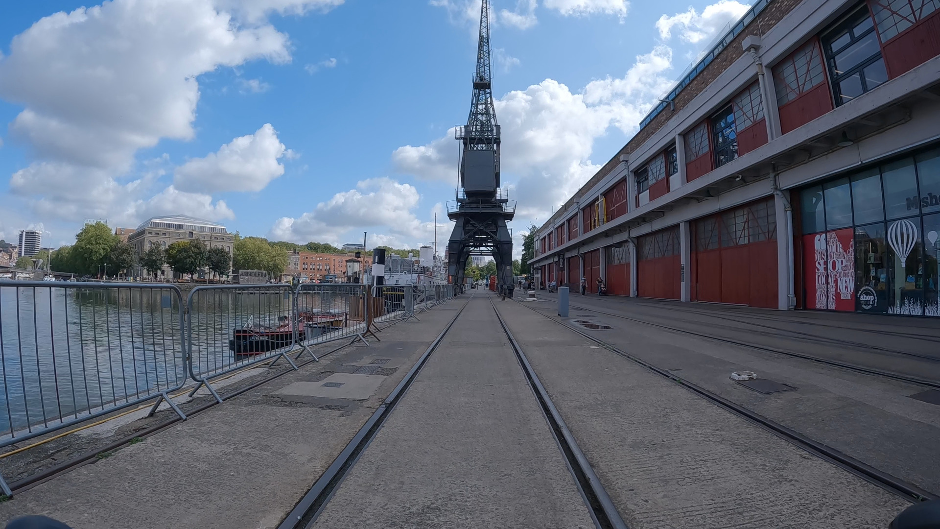
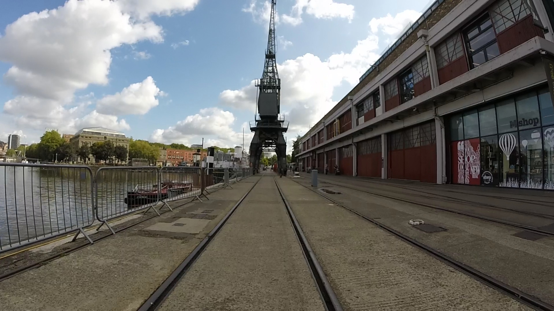
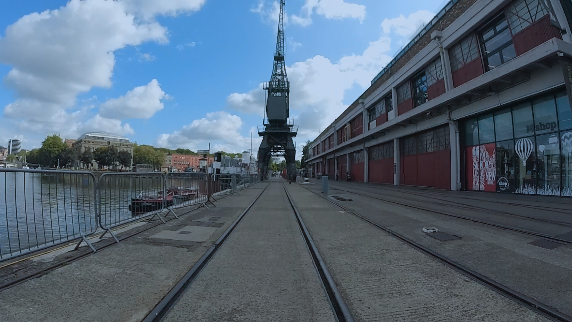
Left: Original left image, Middle: Original right image, Right: Colour corrected right image
Using the Stereo Camera System
Creating Stereo Video Content
The process for stereo capture is as follows,
- Install cameras in hardware mount
- Start both cameras recording
- Clap hands (preferred) or snap fingers within first 10 seconds of recording
- Capture video content
- Run synchronisation, using colour correction LUT
- Encode video, explained below
Encoding to MV-HEVC
Before using the encodemv.py script to create multiview HEVC (MV-HEVC) video, some dependencies are required. The build_tools.sh script can be run from my techdemo docker image and will download and build the necessary tools.
Preprocessing using stsync.py to:
- Find synchronisation timing (note the offset value if you want audio)
- Extract synchronised frames, applying colour correction
Now the video can be encoded and assembled into an MP4 file that FFmpeg can understand,
encodemv.py --input test-rig --leftcal left.yaml --rightcal right.yaml --extcal stereo.yaml --audio GX00001.MP4 --offset 1.5 --output video-mv.mp4The command above performs the following tasks:
- Rectify images
- Output two intermediate raw video streams for left and right views
- Encode into multiview HEVC using x265 built with the multiview flag
- Add missing timing information using MP4Box and output into an intermediate container
- Remux video into an MPEG-4 container with additional audio
It is very important to give consideration to human factors otherwise no one will want to watch the output video. Rectifying images removes, or at least reduces the possibility of vertical disparity. The human visual system is more accustomed to horizontal disparity through vergence; moving the individual eyes in different amounts up or down to fuse the views would lead to eyestrain. Furthermore, during rectification the lens distortion is removed; it would not be possible to view stereo images with different lens distortions in each view.
Rectification may introduce a curved black border to the images, in which case using the --scale parameter with a value below 1.0, will reduce/remove it.
Playing the output video file using VLC or another video player shows a single view. A nice way to verify that stereo content was indeed encoded (note the notation for selecting views in FFmpeg):
LD_LIBRARY_PATH=ffmpeg-8.1.2/libdir;./ffmpeg-8.1.2/ffmpeg -i video-mv.mp4 -filter_complex "[0:v:view:0][0:v:view:1]hstack=inputs=2[v]" -map "[v]" -vb 10M output_sbs.mp4This assumes you used my build_tools.sh script and are in the correct directory. Playing back this video displays the two views:
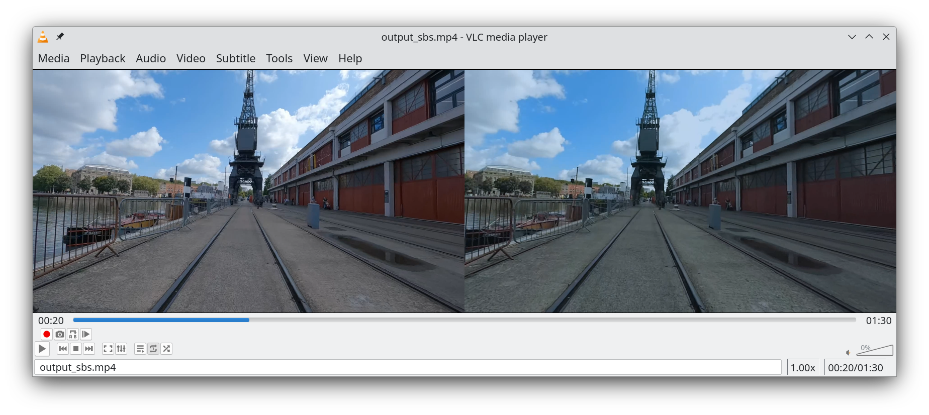
Verifying the multiview video
If the camera is moving the rig is subject to shake and is only suitable for capturing video with a dolly, tripod or gimbal. Handheld panning can be acceptable if the operator can keep the rig steady.
Spatial Video Compatibility
For stereo video to be recognised as Apple Spatial Video, some additional metadata needs to be added to the video file. Both Meta Quest and Apple Vision Pro can understand this format.
Using Mike Swanson's Spatial Video Tool it is possible to add the needed mp4 boxes; however this software only works on Macs with Apple Silicon. Unfortunately I do not currently have access to such hardware so it is not possible for me to develop and validate this part of the workflow.
3D Reconstruction
This section will demonstrate making a metric 3D reconstruction using COLMAP.
Preparation
The process for capturing and creating a 3D model from stereo video begins with the following actions,
- Capture video using the stereo mount; clapping hands in the first 10 seconds for audio synchronisation
- Run the stsync.py script with the camera calibrations already estimated and the colour LUT to get synced and matching colour frames
COLMAP Project Set Up
- mkdir -p project
- Copy the synced stereo rig to project/images/left and project/images/right via the select.sh script to subsample the number of frames, because using all frames would be inefficient and reconstruction would take an excessive amount of time
- Copy rig_config.json to the project directory; note that if it was generated during calibration then the paths to the images may need to be edited
If the rig_config.json file is missing it can be generated from estimated extrinsics using cal2rig in the calibration project.
Sparse Reconstruction
Generate a sparse point cloud reconstruction, using stereocolmap.py:
stereocolmap.py --project project-dir --leftcal hero10-intrinsics.yaml --rightcal hero3-intrinsics.yaml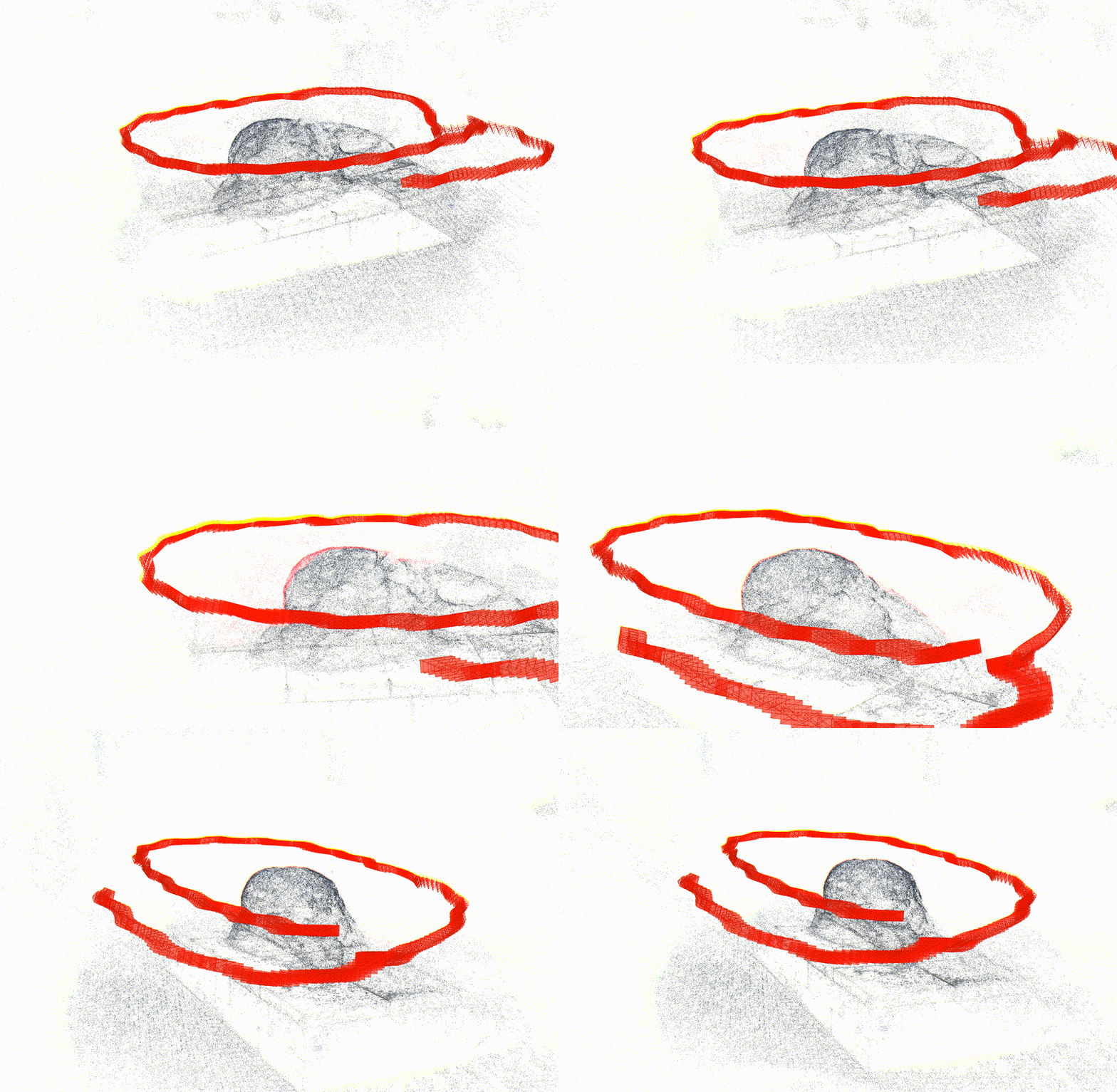
Sparse Reconstruction of the Beetle Sculpture at Anchor Square.
291 stereo frames were registered in the model, consisting of 295k vertices.
Densify, Mesh, Refine and Texture the Reconstruction
Running OpenMVS on the project is mostly straightforward as it understands COLMAP stereo rigs out of the box.
Run stereoomvs.sh to prepare for OpenMVS processing; this script only needs COLMAP in the environment.
stereoomvs.sh project-dirRun runomvs.sh from my reconstruction project to densify the point cloud, generate mesh and texture it.
runomvs.sh project-dirThis script should be run in an environment with OpenMVS tools, such as the OpenMVS docker image.
During the process undistorted images and depth maps will be created for each input image and disk space can fill up quickly. Be aware that if OpenMVS tools run out of memory or disk space they usually fail quietly.
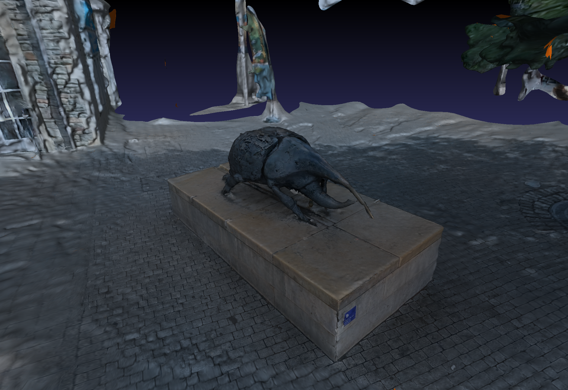
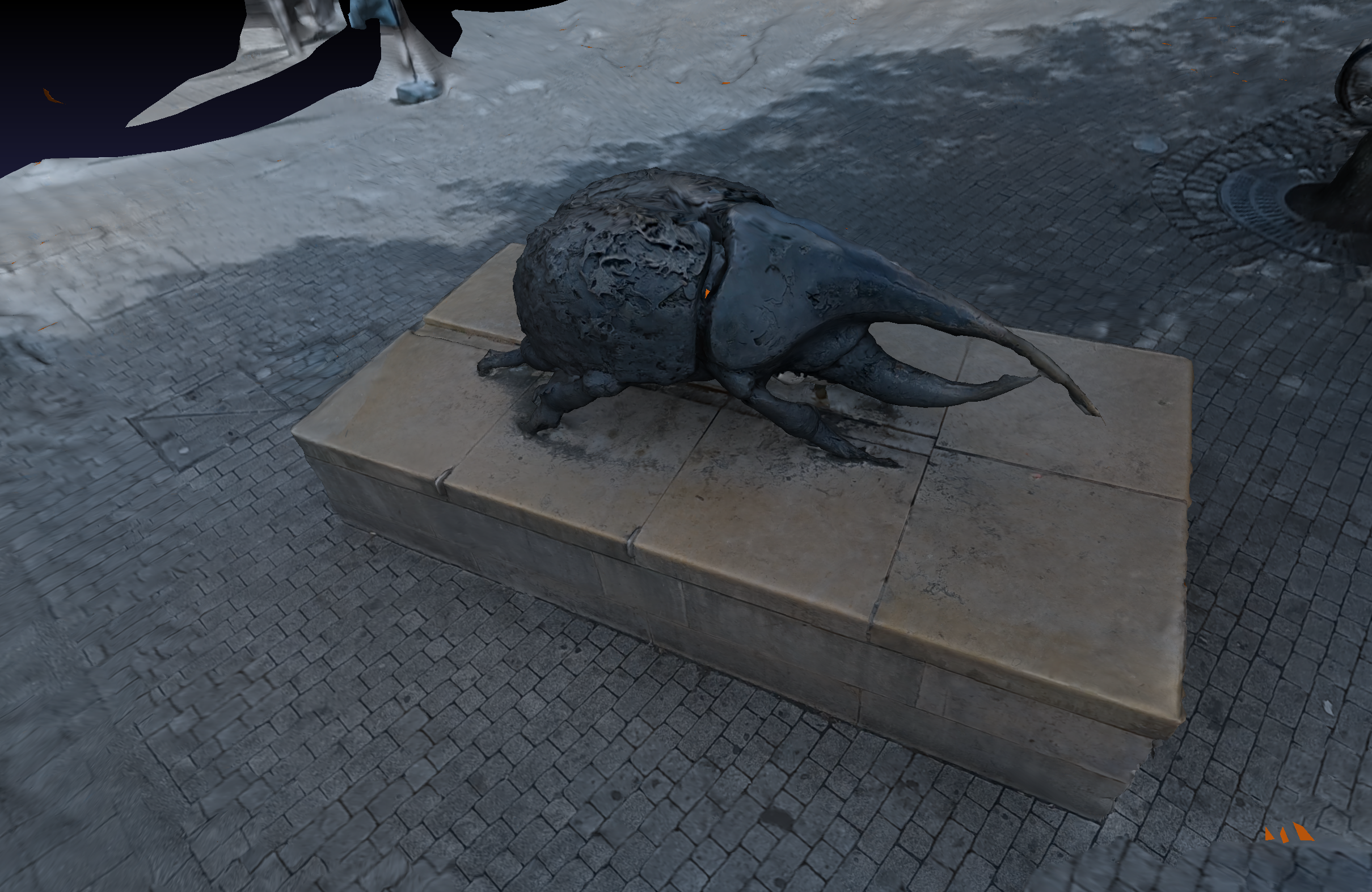
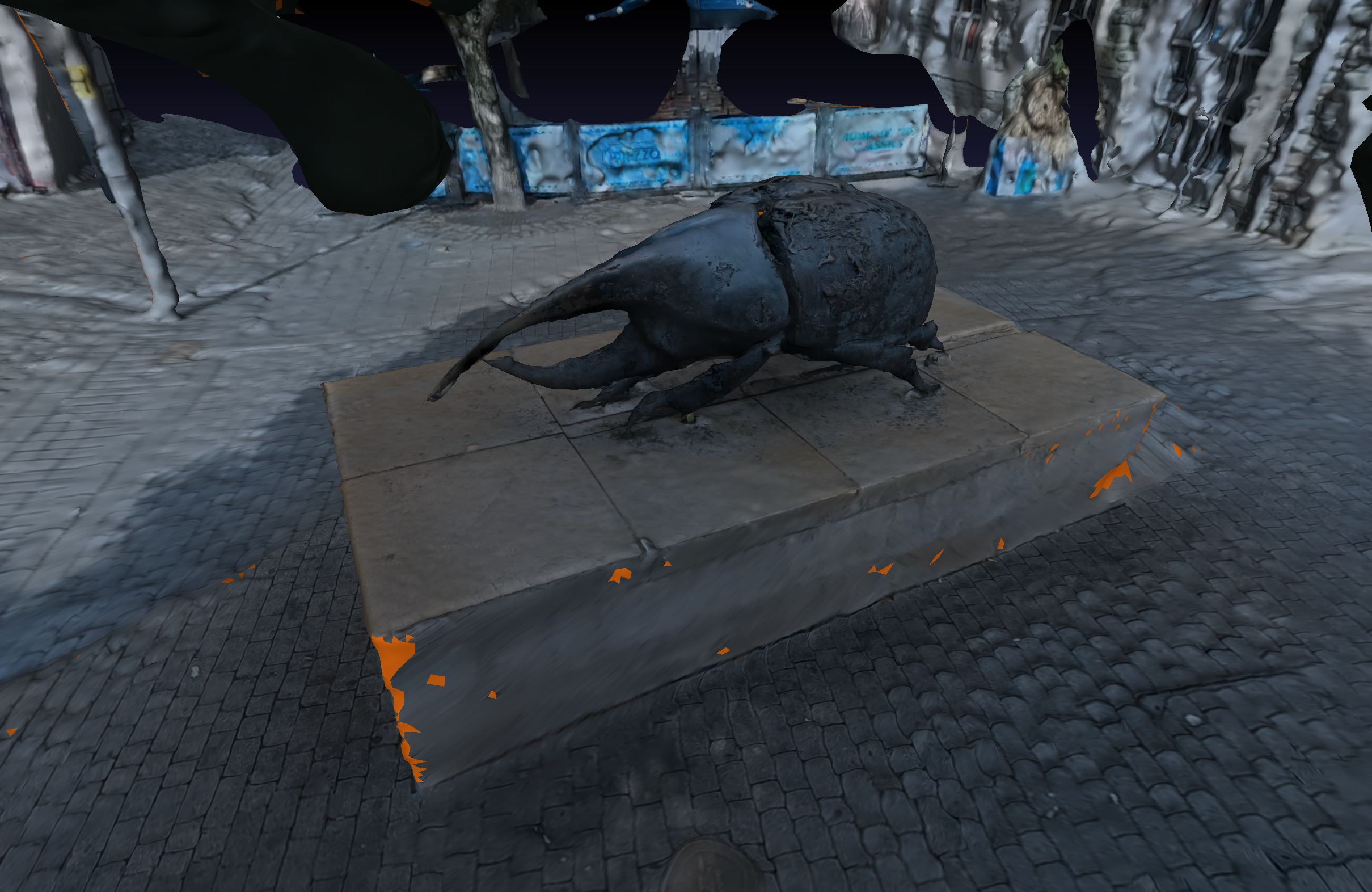
Reconstruction refined and textured by OpenMVS (click on images for larger view).
The densified, refined mesh consists of 476k vertices and 948k faces.
Red regions on the mesh correspond to faces where the texture tool could not find a view in the images/video.
Measurements
In order to check the accuracy of metric reconstruction, I captured video of my Asgard bike shed as this is something I can easily take measurements from. The surface does not have detailed texture so the model has some holes but it's enough to take measurements from.
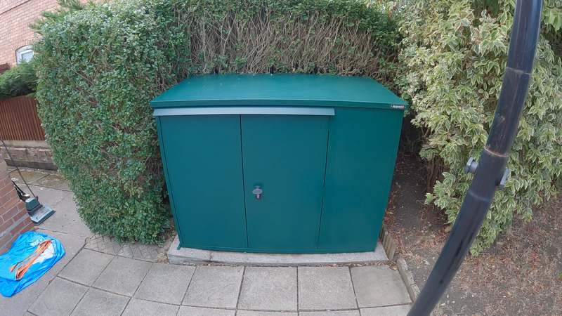
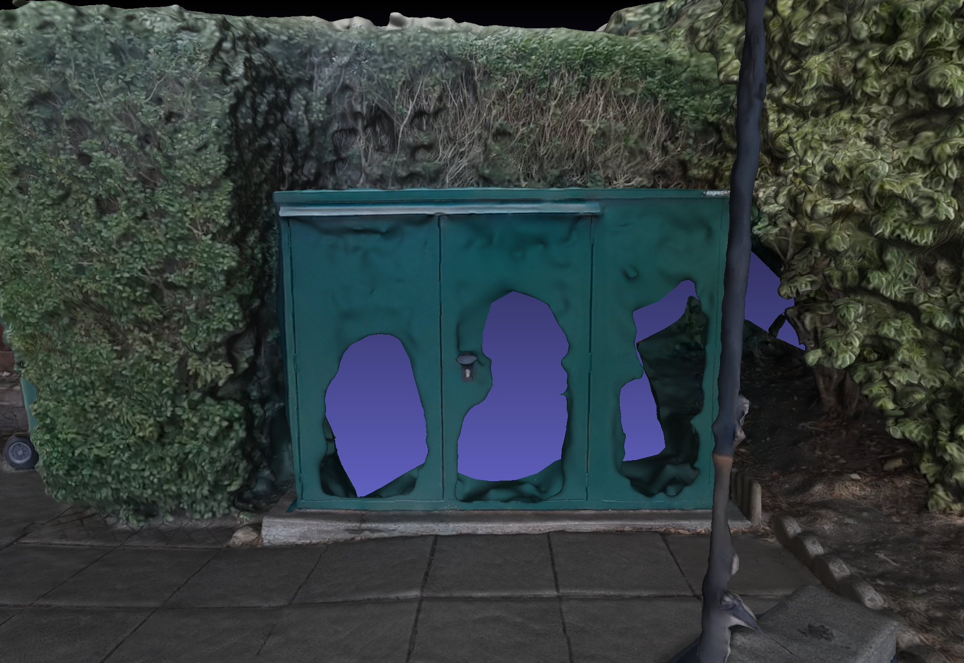
Using MeshLab, I took three measurements of the width and height. Clicking on points on the mesh can be challenging as usually measurements are of external or internal dimensions so clicking a few pixels to the side of the point you want to measure can result in selecting a point that is further back or forward and the measurement is not on the desired surface. The table below also shows the mean of the measurements (Avg) and the ground truth (GT). All measurements are in mm.
| Dimension | Value 1 | Value 2 | Value 3 | Avg | GT |
|---|---|---|---|---|---|
| Width | 1722 | 1691 | 1708 | 1707 | 1790 |
| Height | 1212 | 1225 | 1226 | 1221 | 1305 |
This was using calibration that was generated weeks prior. It would be interesting to do a fresh calibration and rerun the reconstruction to see how much difference that makes.
Based on this result, the reconstruction is accurate to about 10cm. Bear in mind this is not a deep analysis; I have only looked at a single reconstruction and a handful of measurements. Altogether, this is not that impressive; but considering I am using unsynced, mismatched cameras at 1080P with fisheye lenses it's not completely bad either. With a fresher, better calibration and a better reconstruction (more textured surfaces, more frames, better frame selection), perhaps accuracy could be improved slightly, maybe by a couple of cm.
Summary
- Camera rigs must be carefully configured in order to get the best out of them; particularly frame synchronisation and matching image acquisition parameters
- Audio based synchronisation can achieve good results; although genlocked frame synchronisation would be better
- Calibration can be challenging especially when using the fisheye lens model with GoPro cameras
- Colour correction can be efficiently implemented using a 3D LUT which improves visual quality and stereo perception
- Modern video coding standards support stereoscopic video; rectified views were used to avoid cropping and issues with different lens types
- Throughout the design of this system, consideration was given to ensure video would be comfortable to view.
- To make spatial video further compatible with multiple display devices, additional metadata must be added to the multiview video.
- COLMAP and OpenMVS can be used to generate metric 3D reconstructions that take advantage of multi camera rigs
Future Work
- Build Gaussian Splat models from sparse reconstructions and stereo images.
- Develop a tool to add the necessary boxes to multiview video for Apple Spatial Video so it can be integrated into my workflow.
- Use gyroflow with the gyroscope metadata in the Hero 10 video to stabilise the rig in post.
- Rewrite the scripts to reduce the number of steps in running the workflow and produce fewer intermediate files.
Useful Links
These are some web pages I found useful when working on this project.